|
   |
|
Page 8 |
Newsletter 87, Winter 2009 © Hampshire Mills Group |
Technical notes on Barton Watermill, Old Basing, Hampshire
by Luke Bonwick, June 2009
Sheila
Viner and I visited this mill on 23rd March when the restaurant was
undergoing refurbishment. We were impressed by the quality and the completeness
of what remains of the working parts. The conversion to a restaurant has been
carried out sensitively; there is potential for further restoration of the
gearing to working order in the future, dependent on available funds and the
agreement of the mill’s owners.
The
mill’s main range adjoins the mill house and runs NW-SE, straddling the river.
The head pond is positioned to the south of the mill and the bypass channel runs
around its south-eastern end. The original structure, which is timber-framed,
survives amidst several later brick extensions. Weatherboarding to the upstream
elevation of the mill was formerly white-painted and is now tarred.
|
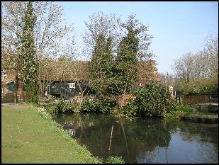
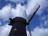
Barton Watermill
Photo Sheila Viner |
|
This is
effectively two mills under one roof, with two fairly narrow internal breastshot
waterwheels driving independent sets of spur gearing. The remains of the
waterwheels, now inaccessible behind glass, could not be measured but are
estimated to be about 3ft wide and 15ft in diameter. The wheel shafts are both
wooden, and old photographs indicate that the wheels were of different patterns.
The SW wheel was of wooden clasp-arm type with two sets of arms, wooden starts
and floats. The NW wheel also had wooden starts and floats, fitted to two sets
of cast-iron arms and rings, the castings forming a hexagon at the centre. The
rings carrying the starts appear to have been of a similar pattern to those at
Longbridge Mill, Sherfield on Loddon. Both sets of gearing are distinctly
different in appearance and the supposition that they date from different eras
can be supported by an analysis of their gear pitch measurements.
Each waterwheel drove two pairs of stones, which were
positioned on the upstream
and downstream sides of each upright
shaft. In the case of the NW set of gearing, the stones were mounted on the
first floor. These have now been taken up and placed against the wall, with the
exception of one French burr bedstone.
The SW
pairs of stones are supported by an elegant wooden hurst frame at a height
mid-way between the ground and first floor levels. This set of gearing appears
to be the older of the two.
It has a cast-iron, 6-armed pit
gear with morticed wooden cogs driving an iron wallower and and a cast-iron,
8-armed great spur wheel with morticed wooden cogs driving wooden nuts. As may
be expected, the pit and spur gears appear to have been cast in halves and
bolted together in situ.
The upright shaft is of wood, with a compass-arm crown wheel set above the
stones which transmitted power to two layshafts positioned on its upstream and
downstream sides. The upright shaft, which extends to bin floor level, is of
interest in that it appears to have been made from several timbers of small
section joined together and secured with iron bands. During the process of
conversion, all the internal woodwork has been liberally varnished with shellac
or something similar, making details of the construction less clearly visible.
On the downstream side of the upright shaft, the bevelled pinion driven by the
crown wheel is of wood, and is probably the original. The sack hoist mechanism,
which survives in the bin floor above, was probably driven from this layshaft.
The layshaft on the upstream side has a cast-iron pinion, and may be an
addition. There are several metal pulleys on this layshaft, together with a
flanged wooden one, though the former arrangement of machinery driven from this
layshaft is now unclear.
Today the bin floor is inaccessible, and this has ensured that the equipment at
this level is safeguarded. In addition to the sack hoist mechanism there are the
remains of a dust extraction system. Photographs of the interior of the mill
taken in the 1960s, prior to its conversion, are available on the Mills Archive
catalogue (www.millsarchive.com). These clearly show the roof rafters which are
now boarded over internally, presumably to meet hygiene requirements.
The gearing driven by the NW waterwheel is almost entirely of cast iron, with
wooden cogs in the pit wheel and the great spur wheel. I was surprised to see
that the cast iron upright shaft terminates at stone floor level and, as a
result, the crown wheel is mounted directly above the great spur wheel, below
the first floor. The crown wheel appears to have driven a single layshaft on its
NW side, which is now missing.
Wooden bridge trees and posts support the gearing and millstones above; the
bridge trees could be raised and lowered with bevel gears operated by decorative
iron handles. The stone nuts were raised out of gear with jacking rings,
operated by large wing nuts. Additional gearing at ground floor level includes a
grain cleaner (probably relocated from elsewhere in the mill) and a
well-executed set of elevators. These have metal viewing windows (originally
glazed?) embossed with the words “Armfield’s System”. A small crusher, also
bearing Armfield’s name, survives directly above on the stone floor.
|
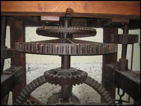
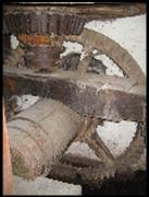
The all-iron NW set of gearing on the
ground floor, set up to drive two pairs of millstones. Note how the crown wheel
is set directly above the great spur wheel on the upright shaft.
The shaft
terminates at stone floor level. |
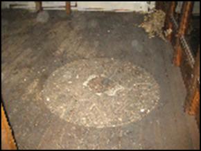
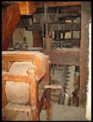
One of the bed stones from the NW set
of gears, set flush with the first floor.
Photos
©
by Luke
Bonwick |
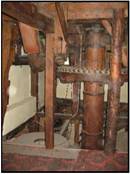
View of the NW set of gears looking
down stream, showing the bridge tree and stone nut. In the foreground is a grain
cleaner. The trunking of a set of elevators can also be seen |
The wheel shaft, pit wheel and wallower of the SE set
of gears. |
The SE set of gears. Two pairs of
stones are set on the hurst frame between ground and first floor levels. Above
them, the crown wheel on the wooden upright shaft transmitted the power to two
lay-shafts |
|
An idea of the dates at which the principal machinery was installed can be
gained by measuring the pitch of the cogs on the crown wheel, spur wheel and pit
wheel for each set of gearing. I compared these measurements against the table
of dates provided by Alan Stoyel in the paper he presented to the SPAB Mills
Section entitled “Perfect Pitch”, published in 1995 (p12). In this paper, Alan
discusses how, over time, the pitch of gears became gradually finer, and that
gear pitches were relatively consistent during particular time periods.
The SE set of gearing yielded the following measurements:
Pit wheel cogs: 3” pitch (5”
face, 1.75” depth)
Great spur wheel cogs: 2.75”
pitch (4” face, 2” depth)
Crown wheel cogs: 3” pitch (3.5” face,
1.75” depth)
A pitch of 3” suggests that the crown wheel was installed pre-1810, and a pitch
of 2.75” for the spur wheel is consistent with this date. The pit wheel has a
pitch of 3”, indicating that it, together with the wallower, was replaced later
than 1810 but before 1880.
The NW set of gearing has pitch measurements as
follows:
Pit wheel cogs: About 2.875”
pitch (5” face and 1.5” depth), indicating a date of 1830-80.
Great spur wheel cogs: 2.375”
pitch (4.125” face and 1.375” depth). Dating: pre-1810 to 1840.
Crown wheel 1.5” P (3” face and 1” depth),
indicating a date of 1880 onwards.
These pitch measurements are slightly
at variance with one another, although this is not supported by the consistent
appearance of the gearing. The pit gears and spur gears could have been made at
a common date prior to 1840. With its fine pitch, the crown wheel may have been
added late in the 19th century (post-1880) to drive
additional machinery.
In
summary, this is an extremely interesting mill, and the fact that it survives
largely intact means that further, detailed study of it remains possible.
Analysis of the gear pitch measurements is a useful tool that can be used in
conjunction with other sources of information, such as documentary evidence, to
arrive at an understanding of how and when the mill was originally constructed,
and how it developed over the course of its working life.
|
   |
|