|
The last issue
covered the history of the mill and the mill
building. 
This article
will describe the milling machinery left as
it was when milling ceased in 1939.
|
|
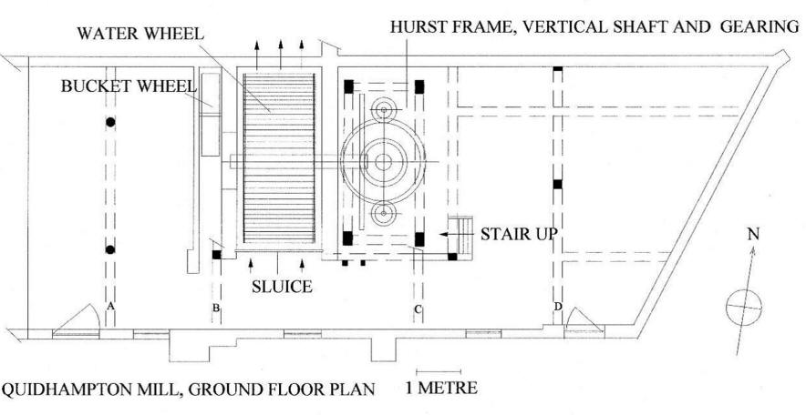
THE GROUND
FLOOR
This is a ground
floor plan of the mill.
There is a single water wheel turning two
pairs of millstones on the floor above.
|
 |
In the western
bay of the building there is a small bucket
wheel driving a water pump. It was inserted
sometime after 1921 to supply a tank up the
hill which provided water to the newly built
Station Bungalows. There is evidence that
this bay may originally have housed a second
water wheel. Firstly, there are three
waterways under the building of which one is
likely to be an overflow sluice leaving two
for water wheels. A waterway runs beneath
this bay. Secondly, there is a grain chute
on the second floor in the right position to
feed grain to the stones of a wheel in this
bay and thirdly, there appears to have been
no other use for this large area. |
|
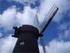
The Water Wheel
The cast iron
wheel is 3.7m in diameter and 1.6m wide,
turning on a circular iron bound wooden
shaft. The wheel was cast in two halves
bolted together and fitted to the shaft by
wooden wedges. This allowed it to be
assembled in the pit without having to
dismantle any of the building. It does not
bear any visible maker’s marks. It is
flanked by brick walls. |
 |
|
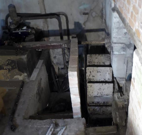
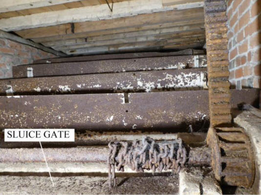
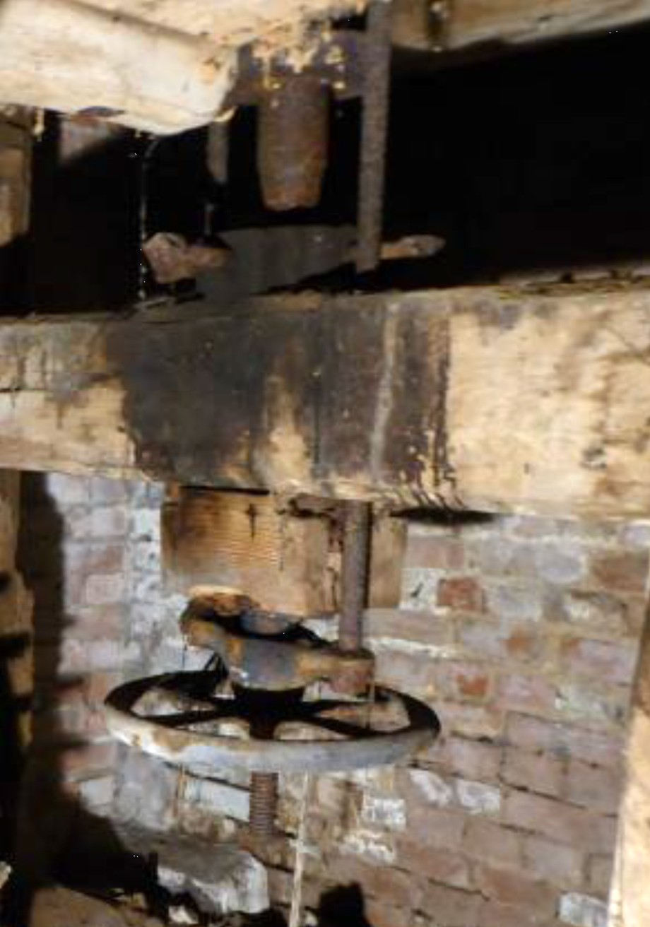
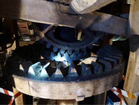
The
Sluice Gate
Here are some
of the iron buckets of the water wheel and
the gear operating an iron sluice gate just
upstream of it, which allowed the miller to
start and stop the wheel.
|
|
|
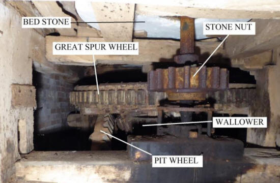
The
Pit Wheel, Wallower
and Great Spur Wheel
The pit wheel
and wallower are cast iron but the great
spur wheel is made of wood. The stone nut
and shaft are of cast iron. The underside
of the stationary bedstone on the floor
above can be seen. It will be noted that
the stone nut and the great spur wheel are
not properly aligned, and the baulk of
timber which acts as the bearing for the
vertical shaft has partially rotted away,
allowing the whole shaft to drop.
|
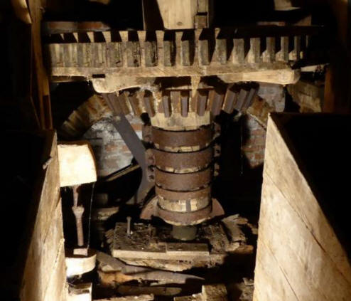
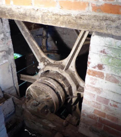
The view below
from the east shows the iron bound wooden
vertical shaft on its bearing, the wallower,
and the great spur wheel. The pit wheel is
behind. |
|
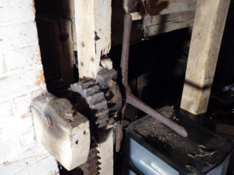
Tentering
Gear
The turn screw
was used for adjusting the height of the
stone nut shaft and thus the gap between the
stones. |
 |
|
THE STONE FLOOR
The Mill Stones
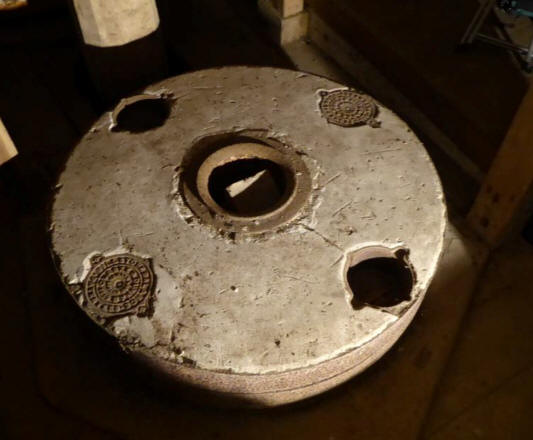
This is one of the two
running stones, 117cm in diameter. It is
probably made of several pieces cemented
together and bound with iron hoops. The
running stone had to be very accurately
balanced about its centre to avoid
vibration. This was done by placing lead
discs in any of the four recesses cemented
into the upper surface.
(Editor's note : all
the stones furniture seems to be missing.) |
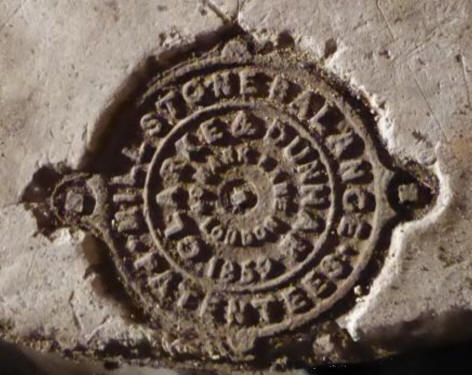
The inscription on the
recess cover reads:
MILLSTONE BALANCE PATENTEES
CLARKE AND DUNHAM, MARK LANE, LONDON, 1869
|
|
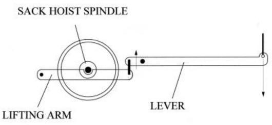
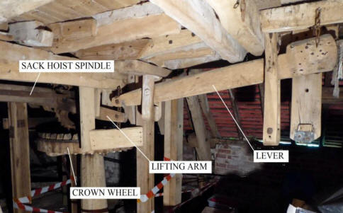
The Crown Wheel and Sack
Hoist
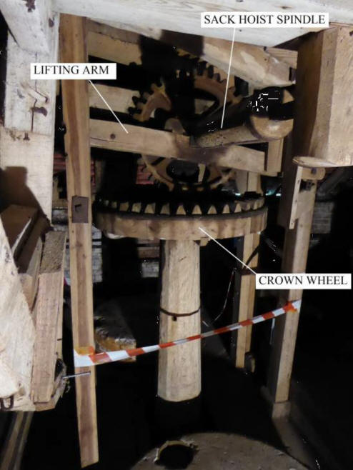
|
The wooden crown wheel
is redundant. A smaller cast iron wheel has
been inserted above it, engaging with a
vertical cast iron wheel which drives the
sack hoist spindle. By putting tension on
two or three turns of rope around the
spindle from the bin floor above, the
operator could use the power of the water
wheel to lift heavy sacks of grain from the
ground to the second floor.
|
|
The lifting arm is
connected by a lever to a cord leading to
the floor above. Allowing the weighted lever
to fall lifted the vertical cogwheel off the
cast iron crown wheel to disengage the sack
hoist.
|
 |
|
The Bins
One of two
grain bins viewed from the first floor. The
spout for feeding grain into the eye of the
runner stone is missing. |
One of two
bins on the second floor for feeding grain
into the hoppers. |
|
THE BIN FLOOR
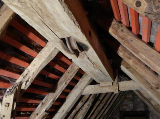
One of two
pulley blocks for the sack hoist rope. |
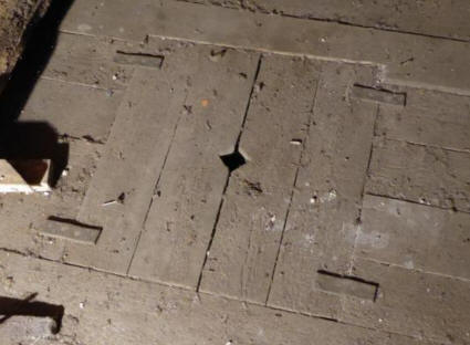
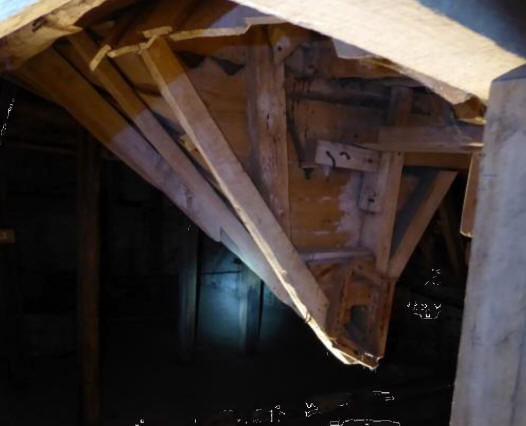
The
upwards-opening trap door for the sack
hoist. The hinges are made of leather. As
a safety measure, the doors close by gravity
when the sack has passed through.
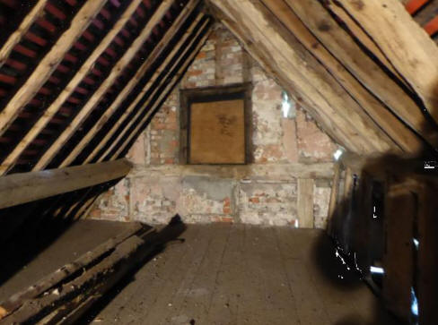
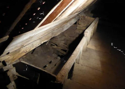
The east end
of the bin floor (left). A new purlin can
be seen on the left. The old ones have been
left lying on the floor. This is where the
miller’s little daughters played ‘houses’ in
the 1920’s. |
| |
|