|
   |
|
Page 5 |
Newsletter 125 Summer 2019 © Hampshire Mills Group |
|
Eureka-style grain cleaners – air flow through a
typical unit
Nigel S Harris & John Brandrick
Drawings © Nigel Harris & John Brandrick. Photos by
Nigel Harris |
|
The S Howes Company of Silver Creek, New York
manufactured the “Eureka” type grain cleaning
machines. Numerous examples of this
machine exist in the UK. After we studied the
construction of some of these machines, we thought
it might be useful to offer some conclusions on the
air flow through a typical unit.
|
|
These machines were widely copied by other
engineering firms and also made under licence. They
exist in various forms, often as scourers, smutters,
and separators, or brush and finishing machines.
The various constructions tend to share similar air
flow routes and purpose with regard to the function
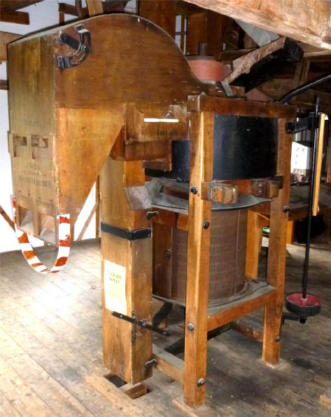
of the air flowing through them. Figure 1 (right)
shows a typical Eureka grain cleaner unit that we
shall consider.
This machine utilises air currents to remove from
the grain both dust and other impurities such as
chaff, straw, shriveled grains and so on. The
construction of the machine to be considered has a
‘smutter section’ as well as an initial screening
stage via shaking perforated metal sieves.
|
 |
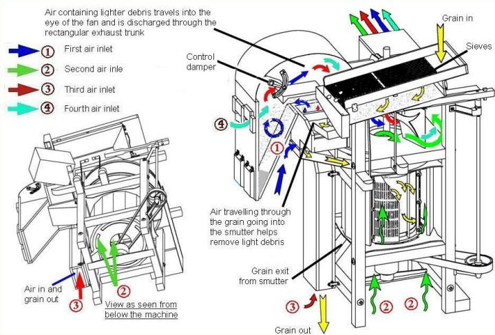 |
There are four air circuits (one being variable)
that take place, before, during, and after the
smutter section. The air flow circuits look fairly
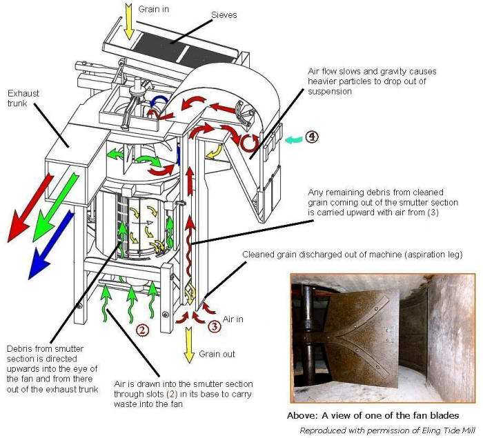
complicated as shown in figures 2 and 3, which are three-dimensional
views of the air flows.
This arrangement appears to be a typical arrangement
although there are noted to be some differences
depending on the model and type of machine. |
|
|
At the heart of the Eureka is a large fan, an
example of an actual fan blade can be seen in the
picture in figure 3, these are fairly large and
flat. The air pressure just at the entrance to the
fan will be the lowest in the machine and will be at
atmospheric pressure at the inlets
1, 2, 3
and
4. The fan acts as a form of compressor and on its
outlet side it discharges to atmospheric pressure in
the exhaust trunk. |
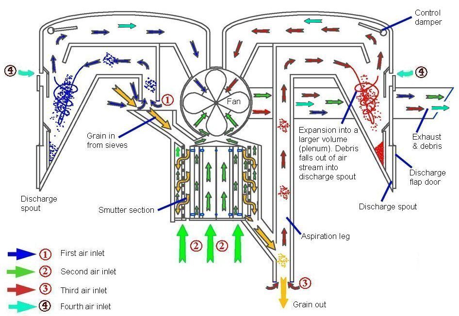
Figure 4 (above) is a simplified schematic showing
the route of the air circuits. (This schematic does
not include the layout of the shaking sieves.) Note
the aspiration legs. Aspiration, or separation by
ascending air currents is used to remove light
particles from the grain. The principle involved is
that particles of different size, shape and specific
gravity have different “terminal velocities”.
Examples of terminal velocities are given by
Lockwood[1], for example. 500 to 700ft per min for
chaff, 700 to 1200ft per min for light straw and
seeds, and 1150 to 1930ft per min for wheat. Wheat
has a higher terminal velocity than light
impurities, so that if a mixture of wheat and light
impurities is dropped into an air current rising at
a suitable speed the wheat will fall through it and
the light particles will be borne away.
A particular feature of Eureka machines is the
expansion chambers or plenums. There are two of
these being vertically separated and alongside each
other in the triangular shaped section. As the air
containing debris is drawn from the duct (or
channel) into the expansion volume the air flow
slows. Solids being carried by the air tend to fall
out of suspension and fall into the tapered
discharge spout in the bottom of the chamber.
Control dampers are provided to adjust the air
throughput.
The debris, which falls into the discharge spout,
remains there until the weight of the accumulated
debris exceeds the force of atmospheric pressure on
the doors of the spout – see figure 5 – whereupon it
falls out of the spout. Also shown in figure 5
are the two air inlet slides (marked 'A'). These
vary the amount of air that can be admitted to the
plenum. If used, air entering the machine here
assists in the removal of light debris from the
plenums towards the fan.
|
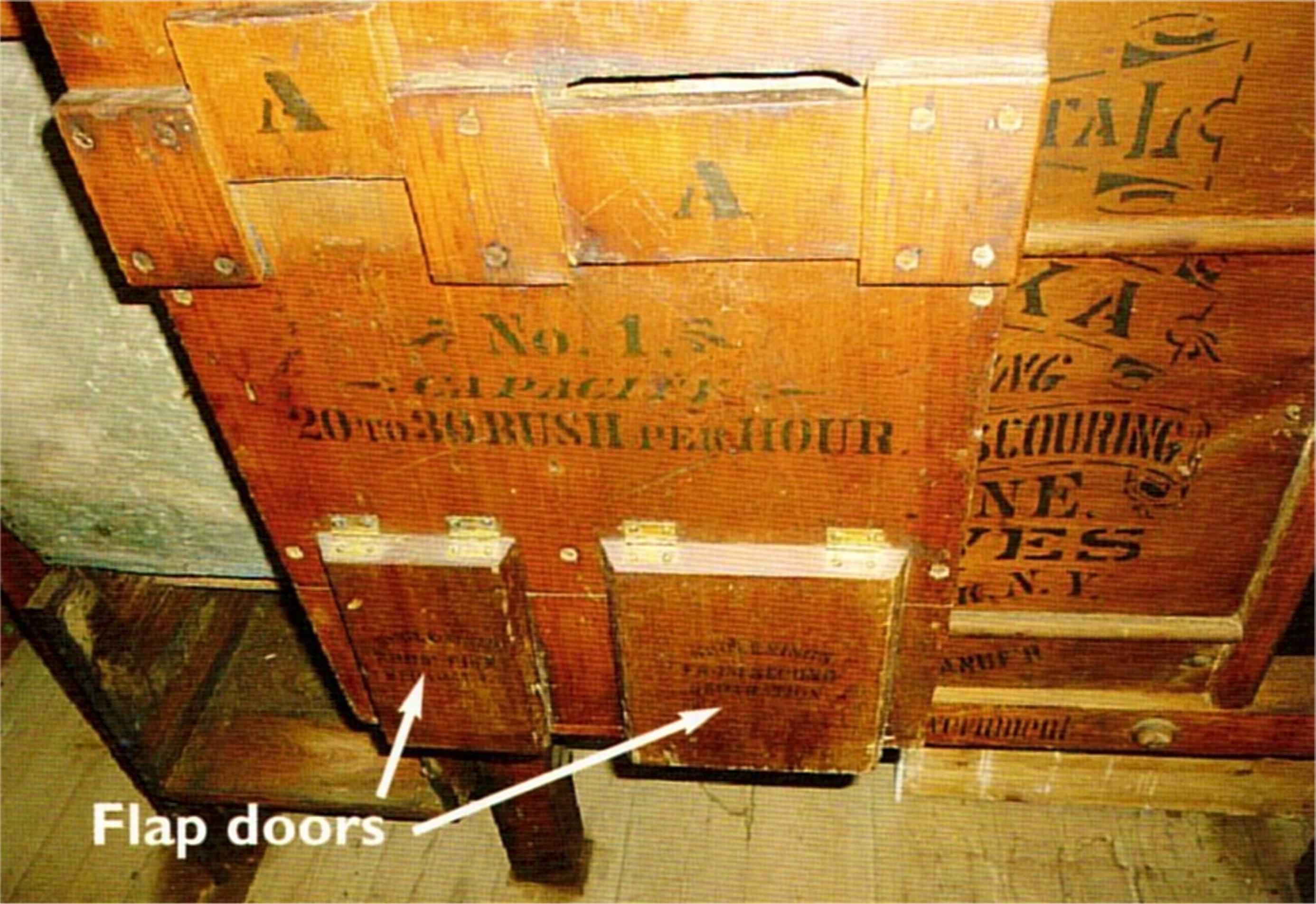
Figure 5: The discharge flap doors and air inlet
sliders (marked 'A') on the discharge trunk |
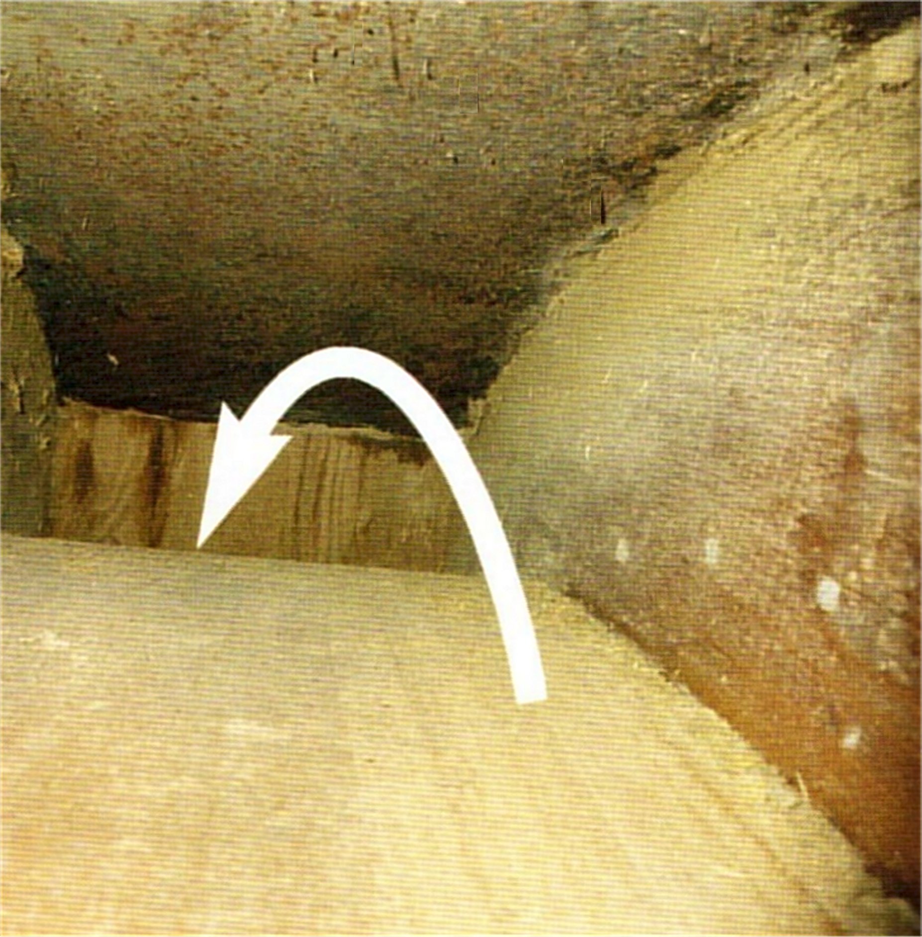
Figure 6: A view inside one of the two air ducts
above the plenum.
Both photos Courtesy of Ifield Watermill, West
Sussex |
|
Figure 6 shows a view inside one of the two air
ducts above the plenum. Note the smooth curving
roof and bottom of the channel. Curves, rather than
abrupt right angle bends, help reduce irregularity
in the air flow. The highest air flow will be in
the centre of the duct with the lowest at the sides
due to drag (friction) with contact along the walls.
Note that the drawings have been based on
information obtained from various sources (see for
example references [2] to [5]), and via external
inspection of various machines. However, both John
and I would welcome sight of any photographs that
show internal details.
References:
[1] Lockwood, J F (1945), Flour Milling. The
Northern Publishing Co Ltd
[2] Greey, W & J G (1901), Greey Toronto Mill
Furnishing Works: Illustrated Catalogue p43 to
45
[3] Robertella, L (2013), http:/www.lousweb.com/Castle%20Valley%20Mill/eureka_brush_machine.htm
and private communications.
[4] Voller, W R (1892), Modern Flour Milling
p53 and 79. John Bellows.
[5] Grimshaw, R. (1882), The Miller, Millwright
and Mill Furnisher p275. Howard Lockwood.
|
| |
|
|
|
|